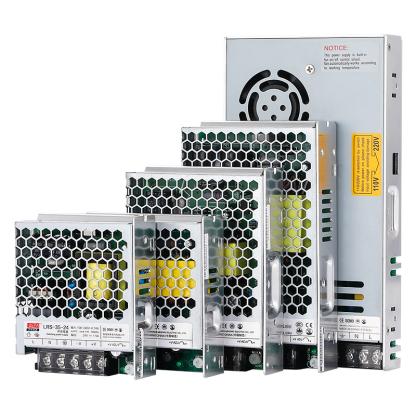
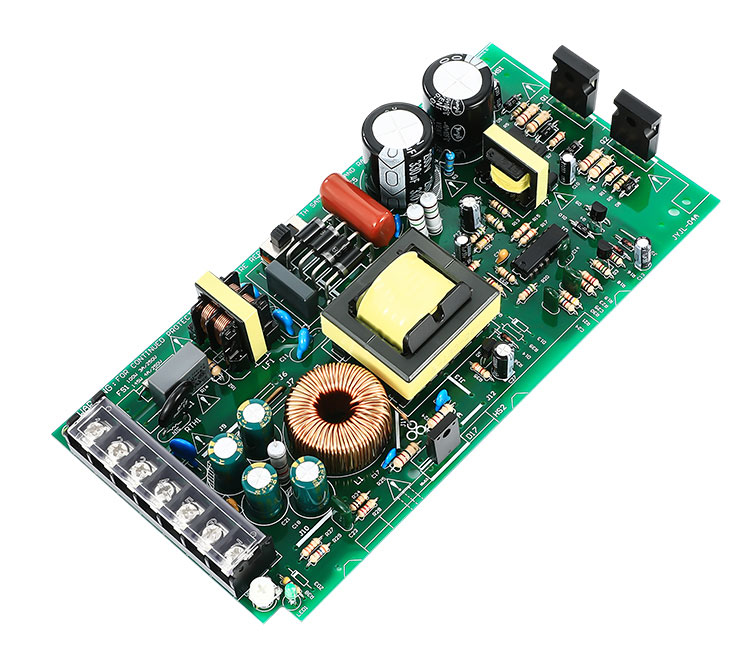
Open Frame Switching power supply diagram explanation
1. Introduction to switching power supply
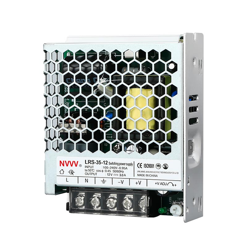
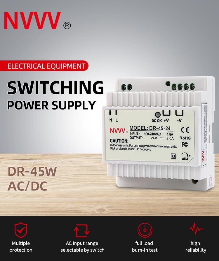
Switching power supply, also known as switching power supply and switching converter, is a high-frequency power conversion device and a type of power supply. Its function is to convert a level of voltage into the voltage or current required by the user through different forms of architecture.
switching power supply
Second, the basic composition of switching power supply
1. Main circuit
Inrush current limiting: limit the inrush current on the input side when the power is turned on.
Input filter: Its function is to filter the clutter existing in the grid and prevent the clutter generated by the machine from feeding back to the grid.
Rectification and filtering: Directly rectify the AC power of the grid into a smoother DC.
Inverter: Transform the rectified DC power into high-frequency AC power, which is the core part of the high-frequency switching power supply.
Output rectification and filtering: Provide stable and reliable DC power supply according to load requirements.
2. Control circuit
On the one hand, samples are taken from the output terminal, compared with the set value, and then the inverter is controlled to change its pulse width or pulse frequency to stabilize the output; on the other hand, according to the data provided by the test circuit, it is identified by the protection circuit and provided The control circuit performs various protection measures on the power supply.
3. Test circuit
Provide various parameters and various instrument data in operation in the protection circuit.
4. Auxiliary power supply
Realize the software (remote) start of the power supply, and supply power for the protection circuit and control circuit (PWM and other chips).
Detailed explanation of switching power supply schematic diagram
5. Basic working principle of switching regulated power supply
Switching regulated power supply connection control methods are divided into two types: width adjustment type and frequency modulation type. In practical applications, width adjustment type is used more often. In the current development and use of switching power supply integrated circuits, most of them are also Pulse width modulation type. Therefore, the following mainly introduces the width-adjustable switching regulated power supply. The basic principle of the width-adjustable switching regulated power supply can be seen in the figure below.
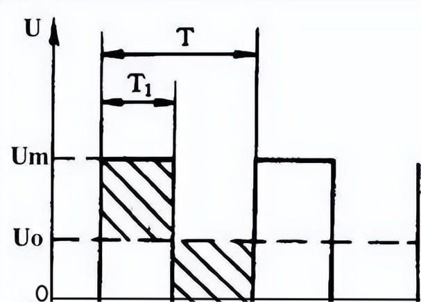
For a unipolar rectangular pulse, its DC average voltage Uo depends on the width of the rectangular pulse, the wider the pulse, the higher its DC average voltage value, and the DC average voltage U can be calculated by the formula, namely
Uo=Um×T1/T
Um is the maximum voltage value of the rectangular pulse
T is the rectangular pulse period
T1 is the rectangular pulse width.
It can be seen from the above formula that when Um and T remain unchanged, the DC average voltage Uo will be proportional to the pulse width T1. In this way, as long as we try to make the pulse width narrow as the output voltage of the regulated power supply increases, we can achieve the purpose of stabilizing the voltage.