You should know! The difference between din rail power supply and switching power supply, working principle
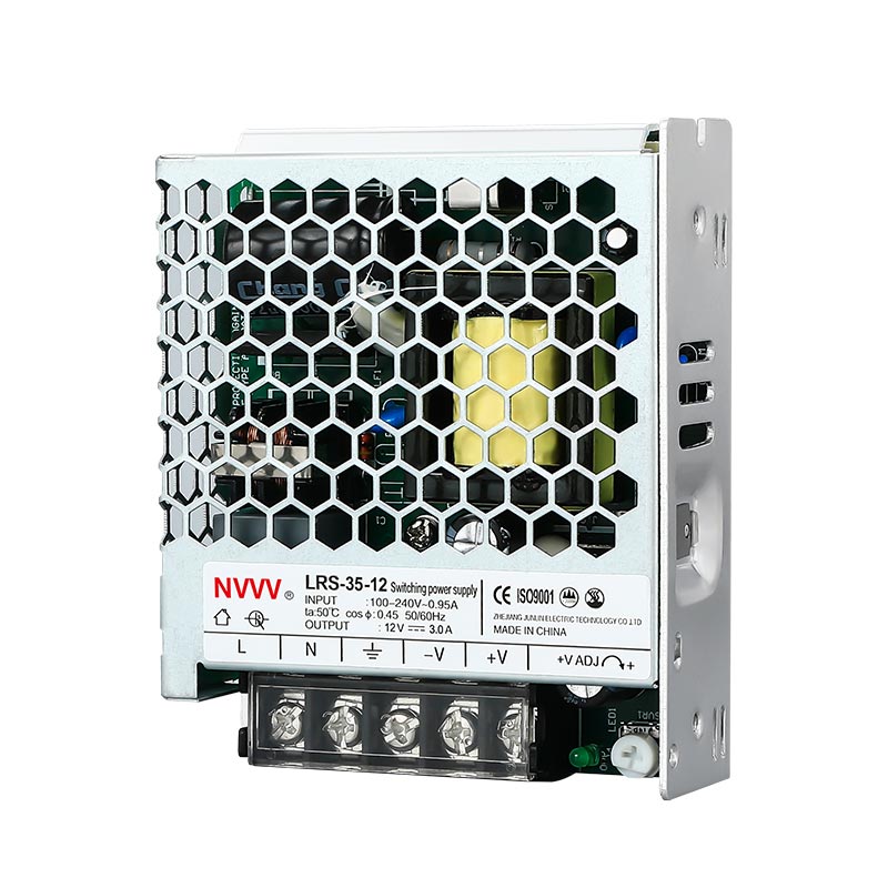
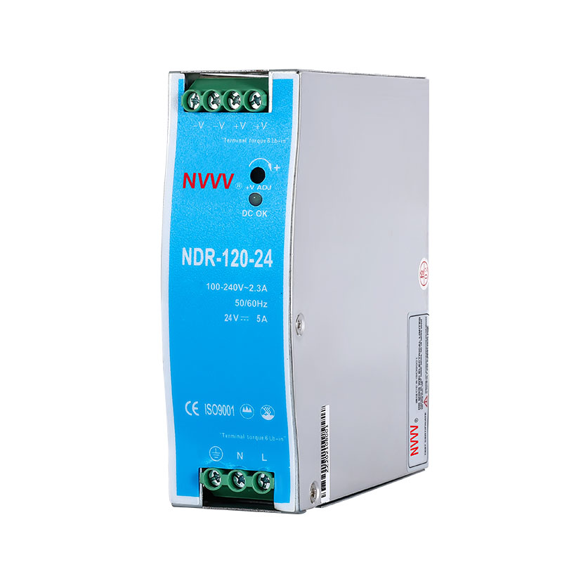
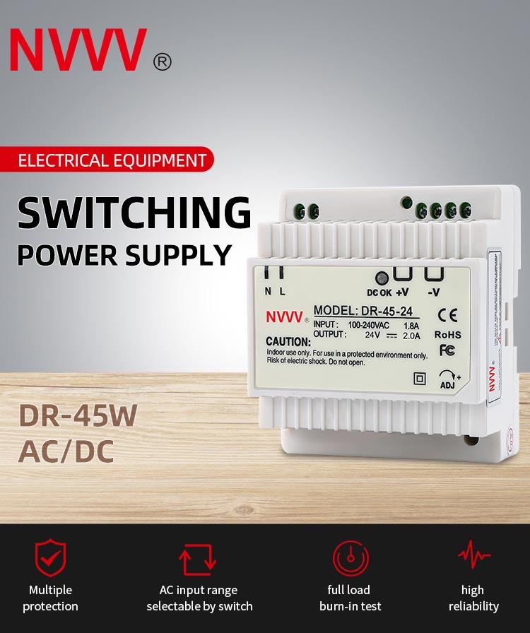
DIN rail power supply is a switching power supply installed through DIN rail. This switching power supply has many different characteristics such as small size and lightweight. Its working principle is to connect the rectifier module to work through AC. For DIN rail power supply and ordinary power supply, There are still differences, not only in terms of names but also in terms of structure and design principles, which will be covered in detail below.
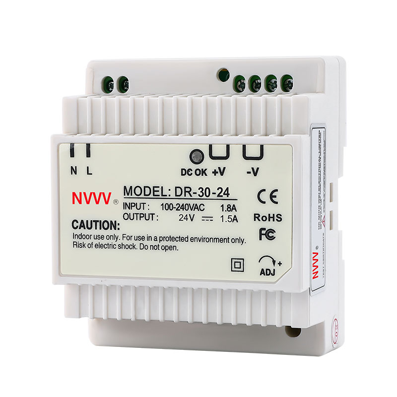
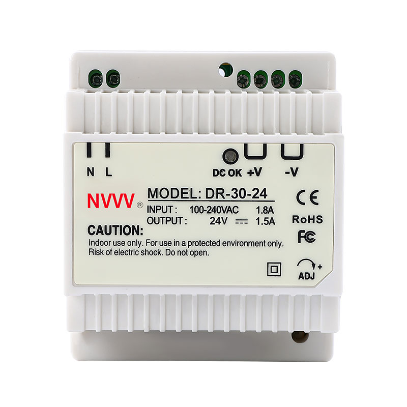
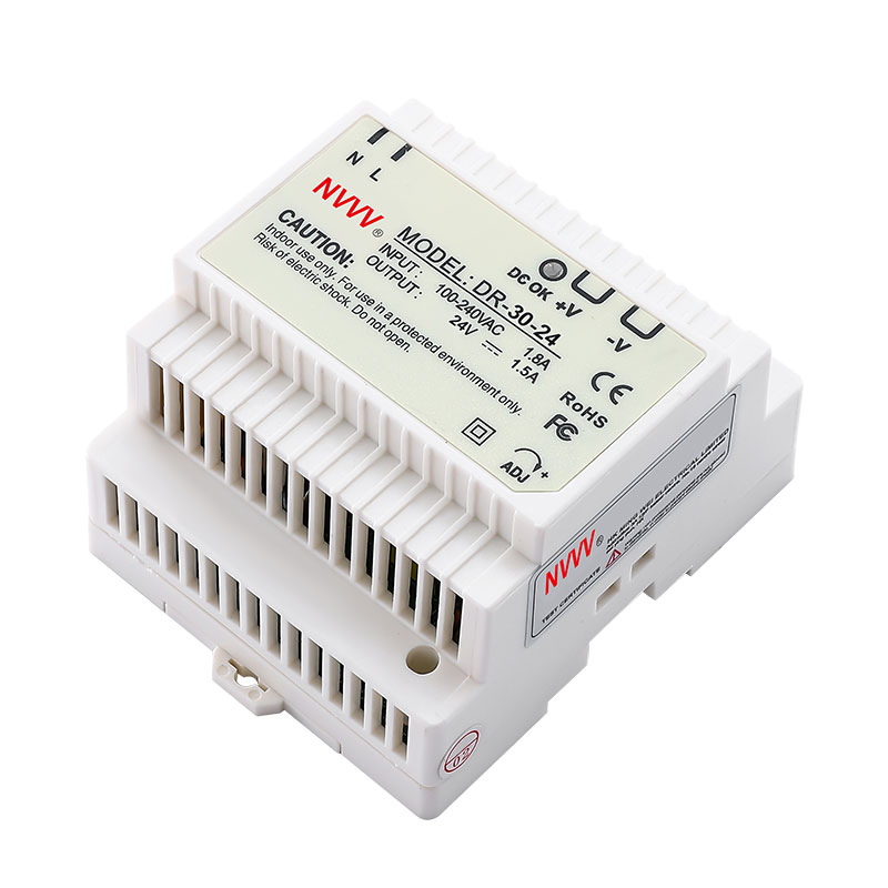
DR-30-24 30W Din Rail Power Supply
The difference between rail power supply and switching power supply
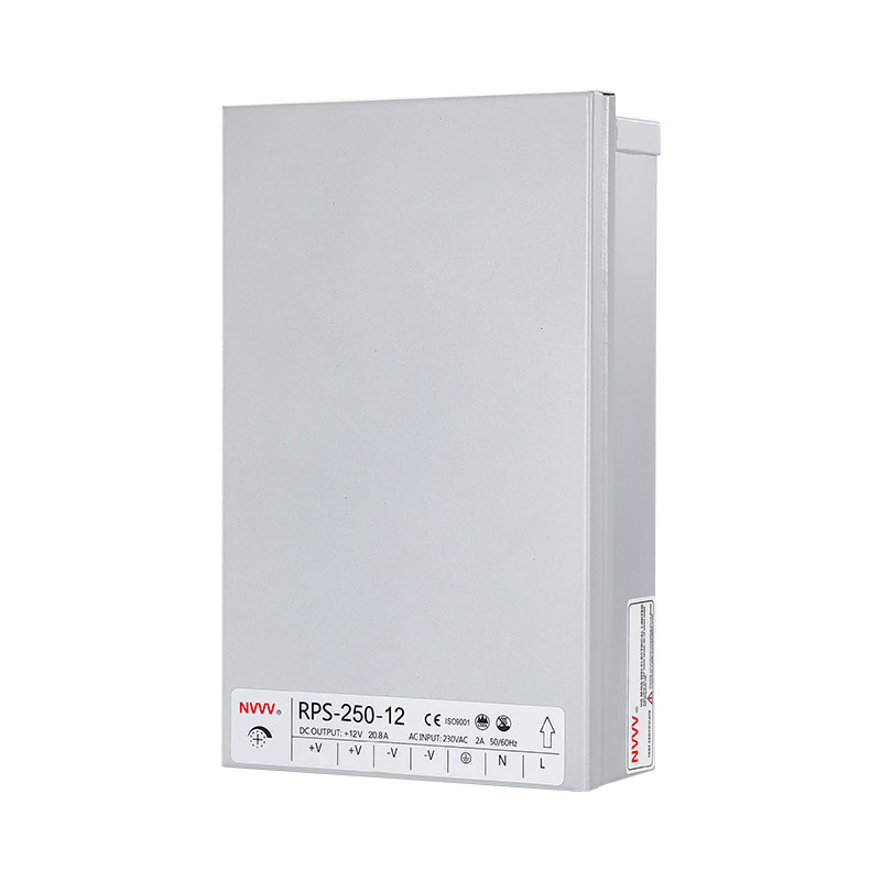
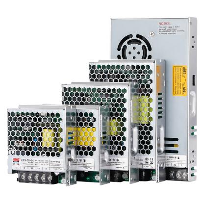
The rail switching power supply is a DC power supply, and the general switching power supply is a constant voltage source. The design problem of rail power supply is volume and price. The main difference between a DIN-rail power supply and an ordinary switching power supply is the difference in packaging form and application environment. Whether it has a fan or not, temperature rise and other issues are mainly different in design. If the heat dissipation is good enough, no fan is needed. Din-rail power supplies are generally used in industrial occasions, with relatively high-performance requirements, and of course, the price is relatively expensive, while ordinary switching power supply applications are diverse, and some occasions will be relatively poor due to cost factors, and fans are needed to help dissipate heat.
The difference between rail-type switching power supply and ordinary:
The main difference between DIN rail and ordinary switching power supply is the difference in packaging form and application environment. Whether there is a fan, temperature rise and other issues are mainly due to different design schemes. If the heat dissipation is good enough, there is no need for a fan. Guide rails are generally used in industrial occasions with high-performance requirements, and of course, the price is relatively expensive. The application of ordinary switching power supply is more diverse, and in some occasions, due to the impact of cost factors, it will be relatively poor, and fans are needed to help dissipate heat.
In principle there is no difference, the rail type is only very suitable for special occasions of rail installation. Installation, maintenance, safety, and convenience. Another kind of rail power supply is more reliable than a general power supply due to the particularity of use and good standardization in safety certification and raw material costs.
There is basically no difference, they are both switching power supplies with the same function. But the type of guide rail is only special, which is completely suitable for the installation of the guide rail, which is convenient for installation, maintenance, and safety.
Another kind of rail power supply is more reliable than a general power supply due to the particularity of use and good standardization in safety certification and raw material costs.
Nowadays, the requirements for power supply are getting higher and higher, especially for some instruments, control, and communication equipment. Moreover, the installation and replacement of the rail power supply is more convenient, occupies less space, and has broader application prospects.
What is the rail power supply for?
The rail power supply is mainly used to monitor the voltage, current, temperature, and other aspects of the equipment so that it can play a very good protective role. DIN rail power supply is relatively convenient to use. For ups power supply, you can actually consult the manufacturer directly when purchasing.
The principle of rail switching power supply:
Connect the AC rectification control module, pass through the filter and three-phase full-wave rectifier to become DC, then connect the high-frequency inverter control circuit to convert DC into high-frequency communication AC, and finally pass through the high-frequency transformer, rectifier bridge, and filter Output stable DC.
The key of the high-frequency circuit is composed of a rectification and filtering circuit, full-bridge conversion power supply circuit, PWM control circuit, voltage regulator, voltage limiting power supply circuit, current regulator and power supply circuit, maintenance power supply circuit and its auxiliary switching power supply principle, etc.
After the working voltage of the three-phase grid (or single-phase power supply) passes through the main switch of the power supply, a rectifier filter is developed to obtain a smooth AC voltage of 520Vdc (300Vdc for the single-phase power supply) that balances the supply and demand of the entire flow circuit
The whole key of the current circuit is a full-bridge conversion power supply circuit composed of a power IGBT control module (or a field effect MOSFET control module). When the PWM output control data signal outputs the power control module according to the respective drivers of the protection controller, the two sets of apex tubes are switched on and off alternately, and a high-frequency single-pulse working voltage is generated in the middle and primary stages of the high-frequency transformer, and the working voltage of the secondary coil is passed through the high-frequency transformer. After the conversion of the frequency transformer, the kinetic energy is displayed to the load through the rectifier.
The output terminals of the guide rail switching power supply are respectively connected to the feedback circuits such as the voltage regulator tube, the speed regulation number, the steady current, and the voltage limiter. When the voltage regulator tube is placed, the voltage regulator tube and the brake power supply circuit are effective. When the output working voltage rises or falls, according to the voltage comparator in the voltage stabilizing circuit, the sampling working voltage is compared with the standard working voltage, and the working voltage of the deviation data signal is added to the PWM control loop to make the PWM output pulse width occur. Relative changes, and then smooth the output operating voltage. If the load current is too high, the brake power supply circuit works, and the output current is limited to the preset value of the brake power.
Similarly, in the case of constant current, the role of the constant current power supply circuit is to stabilize the output current within the preset value, while in the case of overvoltage, the voltage-limiting power supply circuit clamps the output voltage to a limited power generation voltage. When an abnormal phenomenon occurs (such as overvoltage or under voltage protection, overcurrent or overtemperature, etc.), the maintenance data signal is added to the maintenance control circuit, and the output working voltage of the maintenance power supply circuit is added to the PWM power supply circuit to make the PWM power supply The output of the circuit is stopped, and the maintenance track switching power supply is realized.
Reminder: Modern automation equipment has very strict requirements for downtime due to failures. Generally, the operating rate of equipment is assessed in minutes. The convenience and speed of rail power supply are undoubtedly more suitable for the rapid maintenance of automation equipment.